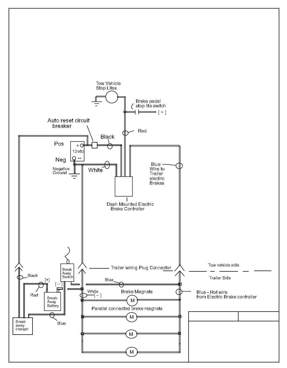
Caravan Electric Brakes Wiring Diagram
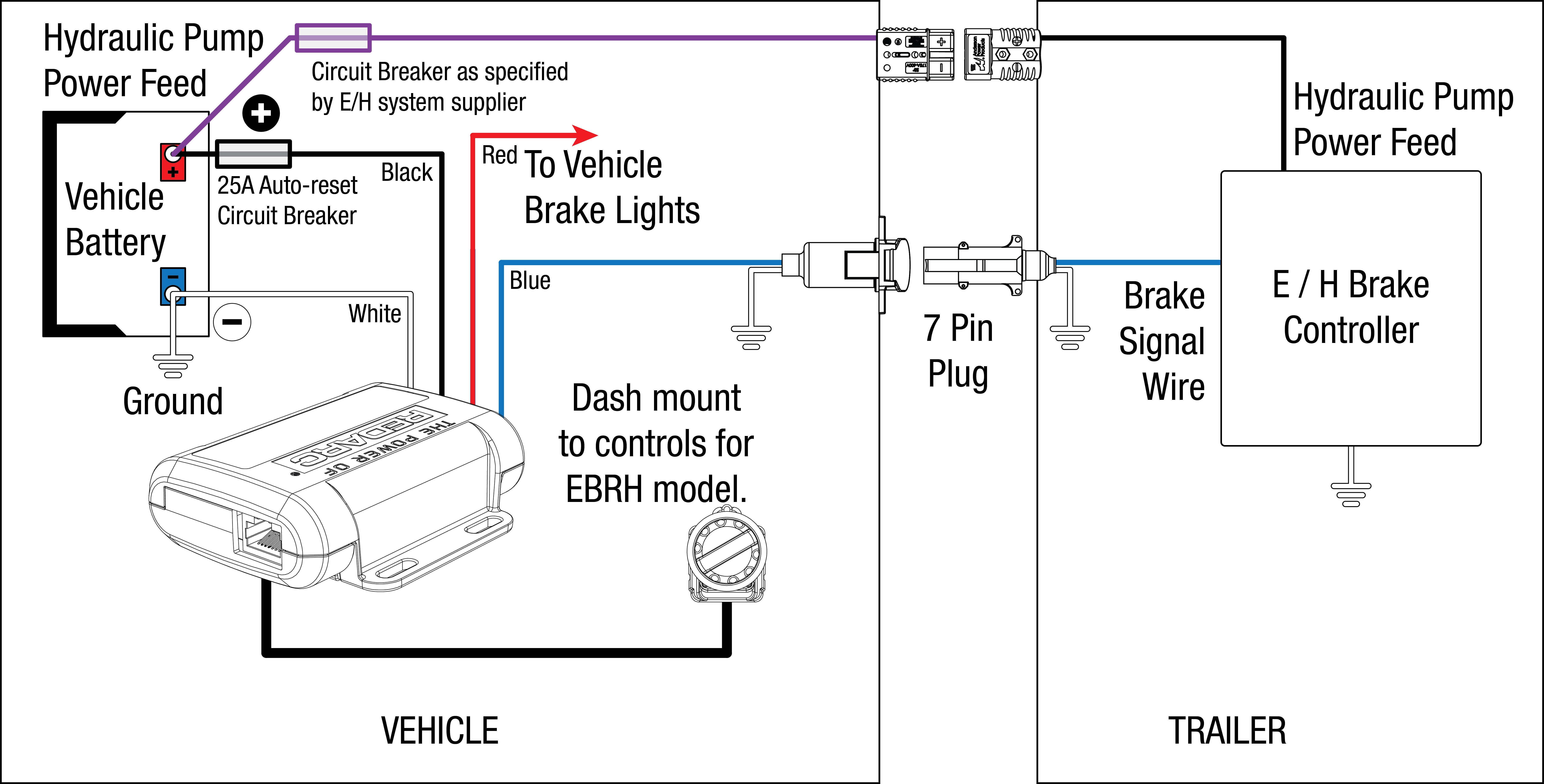
Auxiliary connection is optional, it may be connected to any 12v to 24v constant power source or left unconnected. Caravan electric brake wiring diagram.

Trailer Brake Wiring Diagram Trailer Wiring Diagram
Caravans electric magnets draw 3.2 amps @ 12v each (a) the big mistake when wiring electric brake magnets, is to wire 3mm cable down one side then run more wire across the axle to the other magnet and connect.

Caravan electric brakes wiring diagram. To make wiring a brake controlle not all backing plates are the same. This vehicle is designed not only to travel one place to another but also to carry heavy loads. Electric brake controller wiring diagram.
Caravan electric brakes wiring diagram wiring diagram is a simplified all right pictorial representation of an electrical circuit. Wiring diagram trailer electric brakes best curt trailer brake. The long, additional run of the cable causes more voltage loss than is necessary.
Improving your caravan brake wiring ability. Even manufacturers continue to make this mistake. Otherwise, the arrangement will not work as it ought to be.
Break away systems may be added to the service brake circuit. Trailer wiring diagram a brake controller has only one output wire. Type caravan wiringtrailer parts diagram wiring jope.
View our electrical wiring diagram guides for towbar fitting to power trailer lights and internal caravan electrics. If that wire runs to one wheel, then the other, then the other and the other as demonstrated above, it creates that twisting feeling under braking. Improving caravan electric brake wiring for many owners is near impossible.
Some advice (thank you to ian weal, our illustrious club treasurer and coromal fanatic, for the following advice on electrical wiring) when purchasing a caravan you'll need to add an electric brake controller to your vehicle. Although i have written many, many articles on this same subject, the concept of voltage drop remains elusive. Each component should be set and connected with other parts in particular way.
How electric trailer brakes work. A brake controller wiring installation kit makes light work! May 24, 2020 · wiring diagram.
The ideal current is 3.2a per magnet @ 12v. With this kind of an illustrative guidebook, you'll be capable of troubleshoot, avoid, and full your projects with ease. Nearly all dealers will advise you of this.
Some trailers and caravans are very long and therefore incur more voltage drop than usual. Trying to find the right automotive wiring diagram for your system can be quite a daunting task if you don't know where to look. It shows the components of the circuit as simplified shapes, and the facility and signal links in the company of the devices.
Electric trailer brakes wiring diagram australia, to improve caravan electric braking systems, start by measuring the cable size (copper size) of the electric magnet, it is 1.15mm diameter or close to it. The following diagram is a general guide for wiring common brake controllers into cars.
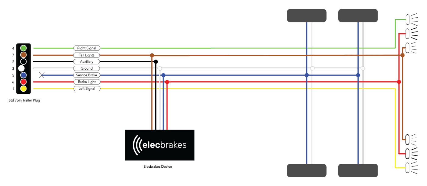
Electric Brake Controller Wiring Diagram Elecbrakes

Mag Brake Controller Wiring Diagram

Curt Discovery Brake Controller Wiring Diagram Free

[DIAGRAM] Wiring Diagram For Caravan Electric Brakes FULL

Wiring Diagram On Trailer Brakes Trailer Wiring Diagram

Electric Trailer Brake Schematic 27
Jayco Electrical Wiring Diagram Professional Camper

Electric Brake Wiring Diagram Australia Home Wiring Diagram
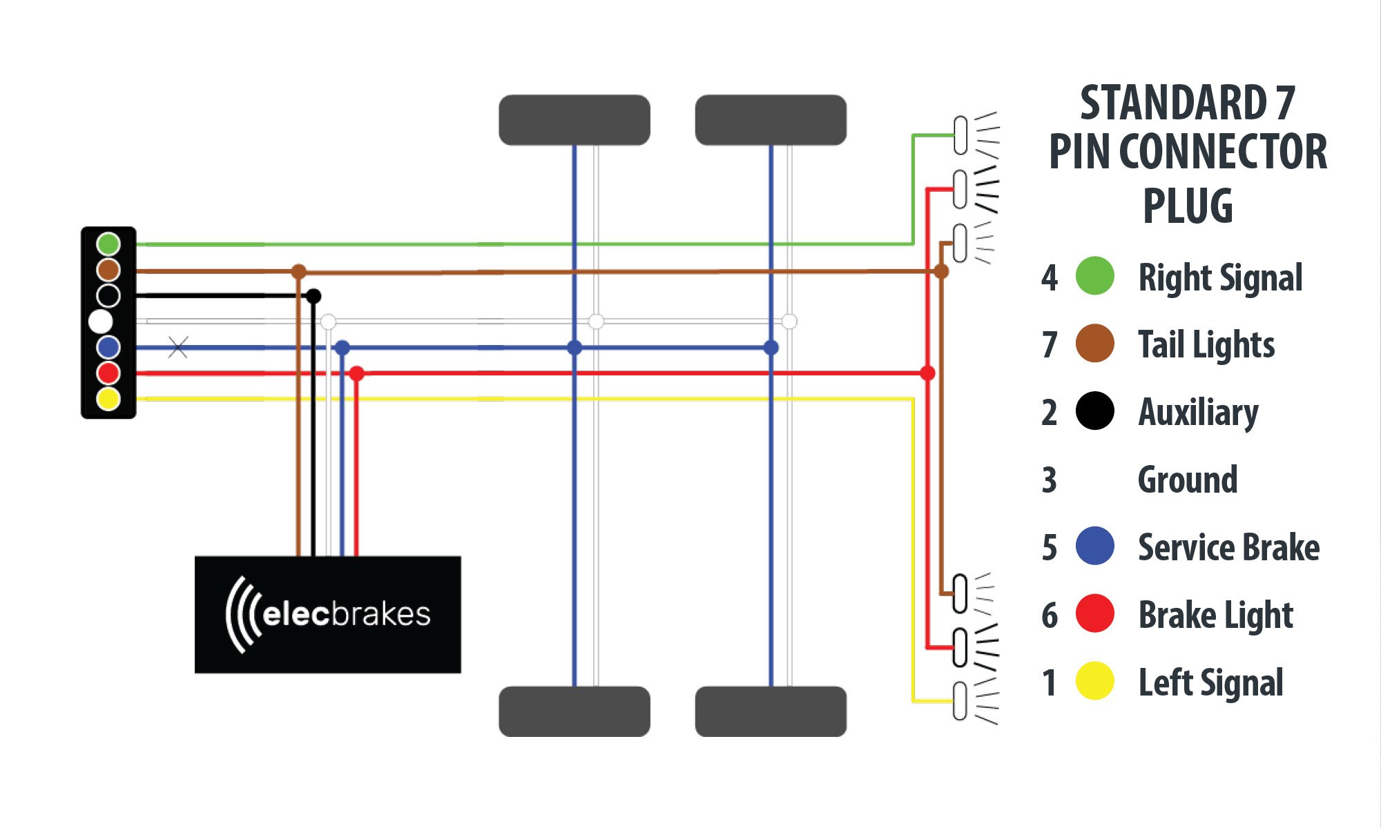
Trailer Wiring Diagram Australia Narva Trailer Plug

Trailer 13 Pin Wiring Diagram Trailer Wiring Diagram

Trailer Breakaway Box Wiring Diagram Trailer Wiring Diagram
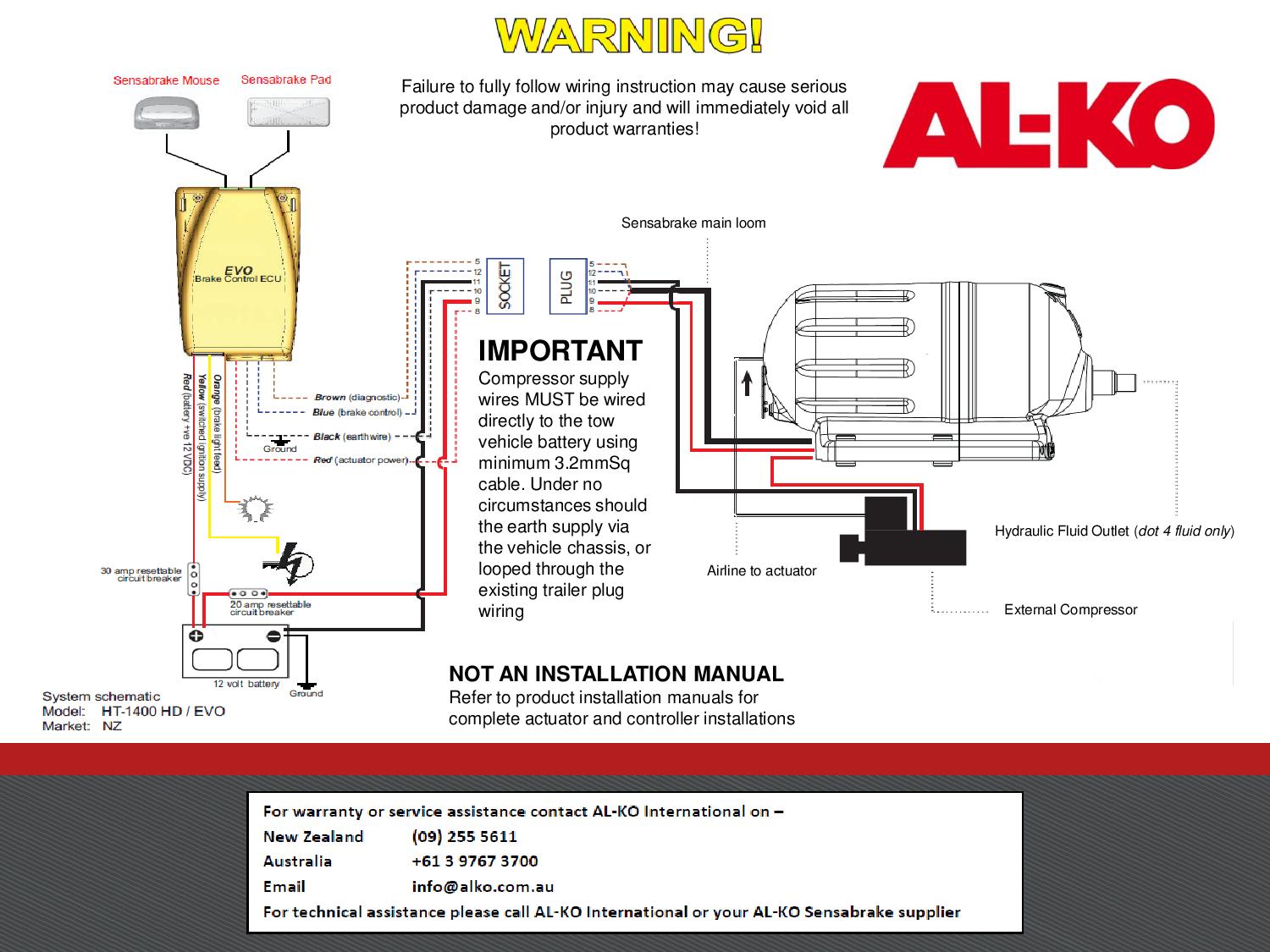
Alko Electric Brakes Wiring Diagram

Trailer Breakaway Box Wiring Diagram Trailer Wiring Diagram
Tekonsha P3 Prodigy Caravan Trailer Electric Brake

Trailer Electric Brake Wiring Diagram 12s Wiring Diagram

43 Tekonsha Wiring Diagram Wiring Diagram Source Online
Hopkins Electric Brake Wiring Diagram for the men in
